Core Products
Detailed specifications, interface logic, and selection criteria for all core monitoring instruments and equipment used in groundwater and drinking water environmental monitoring systems.
5.1 Core Product Overview
The monitoring system relies on a defined set of core products, each serving a specific measurement or data handling function. Product selection must balance measurement performance, environmental suitability, maintenance requirements, and total lifecycle cost. The image below shows the six primary product categories, with their key specifications and application roles.
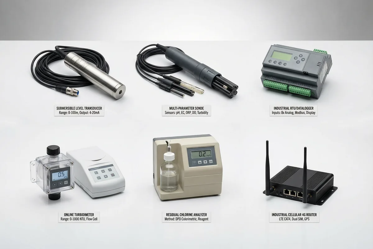
Figure 5.1: Core Monitoring Products — Submersible Level Transducer, Multi-Parameter Sonde, Industrial RTU/Datalogger, Online Turbidimeter, Residual Chlorine Analyzer, and Industrial Cellular Router
Each product category has multiple vendor options with varying performance levels, price points, and maintenance requirements. The selection guidance in this chapter focuses on the minimum performance requirements that must be met for each application, rather than specifying particular brands. Procurement should use these requirements as the basis for technical evaluation criteria in competitive tender processes.
5.2 Interface & Wiring Logic
Understanding the interface and wiring logic between core products is essential for correct system integration. Mismatched interfaces — such as connecting a 4-wire sensor to a 2-wire input, or using the wrong RS485 termination — are a leading cause of commissioning delays and intermittent field failures. The diagram below shows the complete interface connections between all core products, with protocol types, wire colors, and connector specifications.
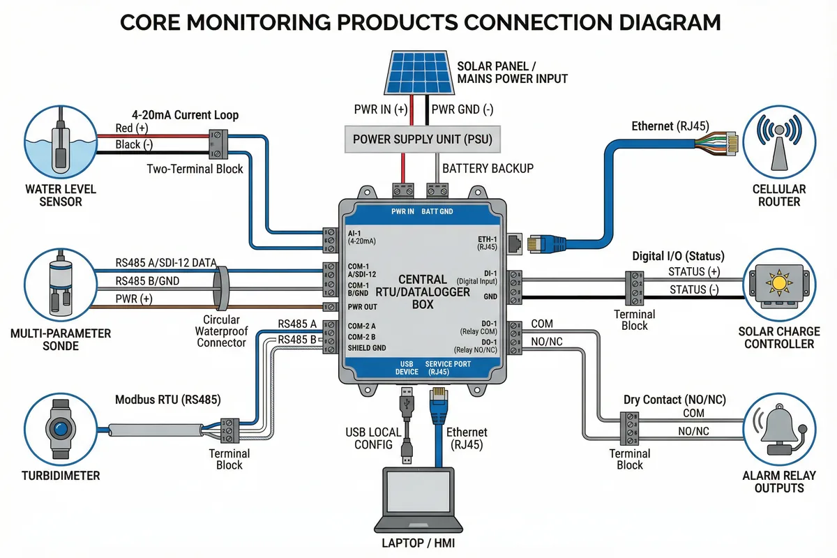
Figure 5.2: Core Products Interface and Wiring Logic — RTU/Datalogger as Central Hub with All Sensor and Communications Connections
The RTU/datalogger serves as the central integration hub, accepting inputs from all field sensors via multiple interface protocols and transmitting aggregated data to the platform via the cellular router. The interface selection for each sensor type follows a clear priority order: SDI-12 for simple sensors in groundwater applications; RS485/Modbus for intelligent sensors requiring bidirectional communication; and 4-20 mA for simple analog sensors where digital communication is not required or available.
5.3 Core Products Feature & Specification Table
The table below provides a comprehensive comparison of all core product categories, covering measurement range, accuracy, interface type, environmental rating, power requirements, calibration interval, and key selection criteria. This table serves as the primary reference for procurement specification writing and technical evaluation.
| Product | Measurement Range | Accuracy | Interface | IP Rating | Power | Cal. Interval | Key Selection Criteria |
|---|---|---|---|---|---|---|---|
| Submersible Level Transducer | 0–10 m / 0–100 m (site-specific) | ±0.05% FS | 4-20 mA, SDI-12, RS485 | IP68 (100 m rated) | 8–30 VDC, <20 mA | 6–12 months | Vented vs. absolute; cable material; anti-corrosion for aggressive groundwater |
| Multi-Parameter Sonde (pH/EC/ORP/DO/Turb) | pH: 0–14; EC: 0–200 mS/cm; DO: 0–50 mg/L | pH ±0.1; EC ±1%; DO ±0.1 mg/L | RS485 Modbus, SDI-12 | IP68 | 12 VDC, <500 mA | 3–6 months | Antifouling option; wiper availability; flow cell compatibility; membrane type for DO |
| Industrial RTU/Datalogger | 8+ analog inputs, 4+ RS485 ports, 4+ digital I/O | ADC: 16-bit; Clock: ±30 s/month | RS485, SDI-12, 4-20 mA, Ethernet, USB | IP40 (panel) / IP65 (field) | 9–36 VDC, <5 W | Annual firmware check | Local storage ≥32 GB; NTP sync; store-and-forward; configurable sampling intervals |
| Online Turbidimeter | 0–1000 NTU (or 0–4000 NTU for raw water) | ±2% of reading or ±0.1 NTU | 4-20 mA, Modbus RTU, relay alarm | IP65 (analyzer) / IP68 (submerged probe) | 24 VAC/VDC, <15 W | Monthly (flow cell cleaning); 6 months (calibration) | Bubble trap requirement; flow cell vs. submersible; auto-cleaning option; scatter angle (90° vs. forward) |
| Residual Chlorine Analyzer | 0–5 mg/L (free chlorine); 0–10 mg/L (total) | ±0.05 mg/L or ±3% of reading | 4-20 mA, Modbus RTU, relay alarm | IP54 (analyzer unit) | 24 VAC, <30 W | Weekly (reagent check); 3 months (membrane/electrode) | DPD colorimetric vs. amperometric; reagent consumption rate; pH compensation; temperature compensation |
| UV254 Analyzer | 0–10 Abs/m (or 0–50 Abs/m for raw water) | ±1% of reading | 4-20 mA, Modbus RTU | IP65 | 24 VDC, <10 W | Monthly (cell cleaning); 6 months (lamp check) | Reagent-free; lamp lifetime; turbidity compensation; flow cell material (quartz) |
| Industrial Cellular Router | LTE Cat4/Cat1; Dual SIM; VPN support | N/A (communications device) | Ethernet (RJ45), RS232/485, USB | IP30 (panel) / IP65 (outdoor) | 9–36 VDC, <10 W | Annual firmware update | Dual SIM for carrier redundancy; VPN client built-in; watchdog timer; -40 to 70°C operating range |
| Solar Power System | Panel: 20–200 W; Battery: 20–200 Ah | MPPT efficiency ≥97% | Digital I/O (status), RS485 (MPPT data) | Panel: IP65; Battery: IP55 | Output: 12/24 VDC | Annual (battery capacity test) | LiFePO4 vs. AGM; MPPT vs. PWM; low-temperature performance; cycle life |
5.4 Product Selection Guidance
Water Level Sensors: Vented vs. Absolute
The choice between vented (gauge) and absolute pressure transducers is one of the most consequential decisions in groundwater monitoring design. Vented sensors use an atmospheric reference tube inside the cable to compensate for barometric pressure changes automatically, providing direct water level readings without post-processing. Absolute sensors measure total pressure (water + atmosphere) and require barometric compensation using a separate barometer or a reference sensor at the surface. Vented sensors are preferred for most groundwater applications, but their vent tubes are vulnerable to moisture ingress and require regular inspection. Absolute sensors are preferred for deployments where cable management is difficult or where the vent tube integrity cannot be assured.
Multi-Parameter Sondes: Antifouling Strategies
Biofouling, iron/manganese precipitation, and algae growth are the primary causes of sensor drift and data quality degradation in groundwater sondes. Antifouling strategies include mechanical wipers (effective for optical sensors), copper-alloy guard rings (effective for biological fouling), and anti-biofouling coatings. The appropriate strategy depends on the specific fouling mechanism at the site, which should be assessed during the site survey. Flow cells — which continuously flush the sensor with fresh sample water — significantly reduce fouling compared to static deployment but require a pump and bypass piping.
Turbidimeters: Flow Cell vs. Submersible
Flow cell turbidimeters draw a sample through a controlled measurement cell, providing stable, bubble-free readings but requiring bypass piping, flow control, and regular cleaning. Submersible turbidimeters are deployed directly in the water body, eliminating bypass piping but requiring careful placement to avoid interference from suspended sediment, bubbles, and biofouling. For drinking water applications, flow cell turbidimeters are strongly preferred because they provide more reproducible readings and are easier to calibrate and maintain. For raw water intake monitoring, submersible probes may be used as a supplement to flow cell instruments for continuous trend monitoring.
Residual Chlorine: DPD vs. Amperometric
DPD colorimetric analyzers use chemical reagents to produce a color reaction proportional to chlorine concentration, then measure the color photometrically. They provide excellent accuracy and selectivity but require regular reagent replenishment and disposal. Amperometric analyzers use an electrochemical cell to directly measure the oxidizing power of the sample, requiring no reagents but needing regular membrane replacement and pH/temperature compensation. For compliance monitoring, DPD colorimetric is generally preferred due to its better selectivity and lower susceptibility to interfering species. For continuous process control where reagent logistics are a concern, amperometric sensors may be preferred.