Architecture Design
Detailed system topology, network architecture, and equipment wiring design for groundwater and drinking water monitoring systems — from field station layout to platform integration.
4.1 Typical System Topology
The monitoring system is organized into three distinct layers: the Field Layer containing all measurement and data acquisition equipment at monitoring points; the Network Layer providing secure, resilient data transport; and the Platform Layer delivering all data management, alarming, and reporting functions. This three-layer architecture provides clear separation of concerns, enabling independent scaling and maintenance of each layer without disrupting the others.
Groundwater well stations (GW-1 through GW-n) connect to the platform via cellular LTE with VPN encryption, while drinking water plant nodes (DW-A, DW-B) use fiber optic connections for higher bandwidth and lower latency. All field devices communicate through a secure VPN gateway before reaching the platform, ensuring that no field device is directly exposed to the internet. The firewall enforces strict ingress/egress rules, and all access is logged for audit purposes.
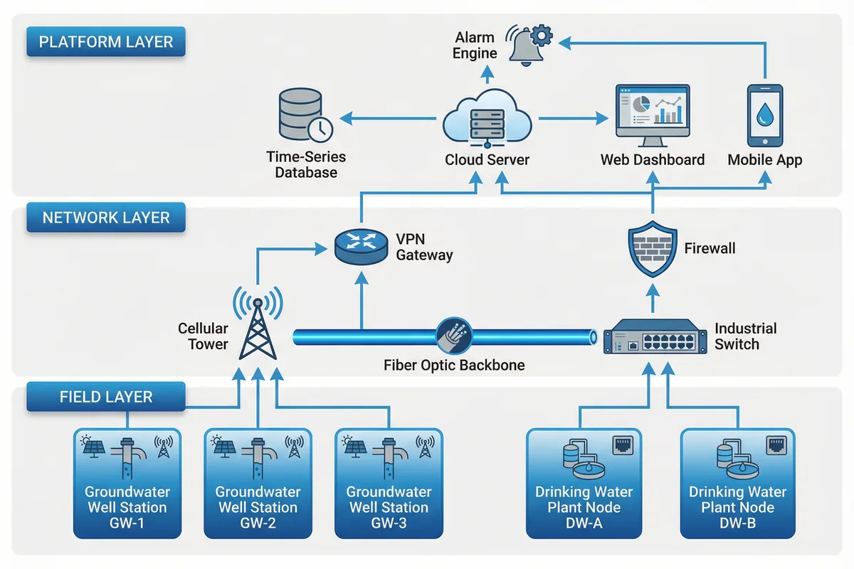
Figure 4.1: Typical System Topology — Three-Layer Architecture with Field Stations, Network Layer, and Cloud Platform
The topology supports both cloud-hosted and on-premises platform deployments. For cloud deployments, the platform layer runs in a managed cloud environment with geographic redundancy. For on-premises deployments, the platform server is hosted within the customer's network, with the VPN gateway providing secure access for remote field stations. Hybrid configurations — where some data is processed at the edge and only aggregated results are sent to the cloud — are also supported for bandwidth-constrained deployments.
Station Classification and Network Assignment
| Station Class | Typical Application | Network Path | Data Interval | Alarm Latency Target |
|---|---|---|---|---|
| GW-1 | High-risk groundwater wells (industrial, contamination risk) | LTE → VPN → Platform | 15 min | ≤30 min |
| GW-2 | Standard groundwater monitoring wells | LTE → VPN → Platform | 60 min | ≤2 h |
| GW-3 | Remote baseline wells (low risk) | LTE or LoRa → Gateway → Platform | 4 h | ≤8 h |
| DW-A | Critical drinking water nodes (intake, disinfection) | Fiber → Industrial Switch → Platform | 1 min (continuous) | ≤3 min |
| DW-B | Standard drinking water nodes (distribution, storage) | Fiber or Ethernet → Platform | 5 min | ≤15 min |
4.2 Network Architecture & Security
Network architecture for environmental monitoring systems must balance accessibility (operators need to access data from multiple locations) with security (field devices must not be exposed to cyber threats). The recommended architecture uses a defense-in-depth approach with multiple security layers, ensuring that a breach of any single layer does not compromise the entire system.
All field-to-platform communications use TLS 1.2 or higher encryption. Field devices authenticate using device certificates, not shared passwords. The VPN gateway terminates all field device connections and presents them to the platform as a single, controlled interface. Role-based access control (RBAC) ensures that operators can only access data and functions appropriate to their role, and all access attempts are logged with timestamps and user identity.
| Security Layer | Mechanism | Implementation | Verification |
|---|---|---|---|
| Physical | Locked cabinets, tamper switches, CCTV | IP65+ enclosures, tamper seals, vibration sensors | Annual physical security audit |
| Network | VPN tunnel, firewall, network segmentation | IPSec/OpenVPN, stateful firewall, VLAN separation | Penetration test, firewall rule review |
| Transport | TLS encryption, certificate authentication | TLS 1.2+, device certificates, MQTT over TLS | Certificate expiry monitoring |
| Application | RBAC, audit logging, session management | Role-based permissions, immutable audit log, session timeout | Access log review, privilege audit |
| Data | Data integrity, backup, retention | Checksums, encrypted backups, retention policy enforcement | Backup restoration test, data integrity check |
4.3 Equipment Wiring Design
Proper wiring design is critical for system reliability and maintainability. Poor wiring — incorrect wire gauges, missing shields, inadequate surge protection, or improper grounding — is responsible for a significant proportion of field failures. The wiring diagram below shows the complete internal wiring of a standard groundwater monitoring station cabinet, including power, signal, and communications connections.
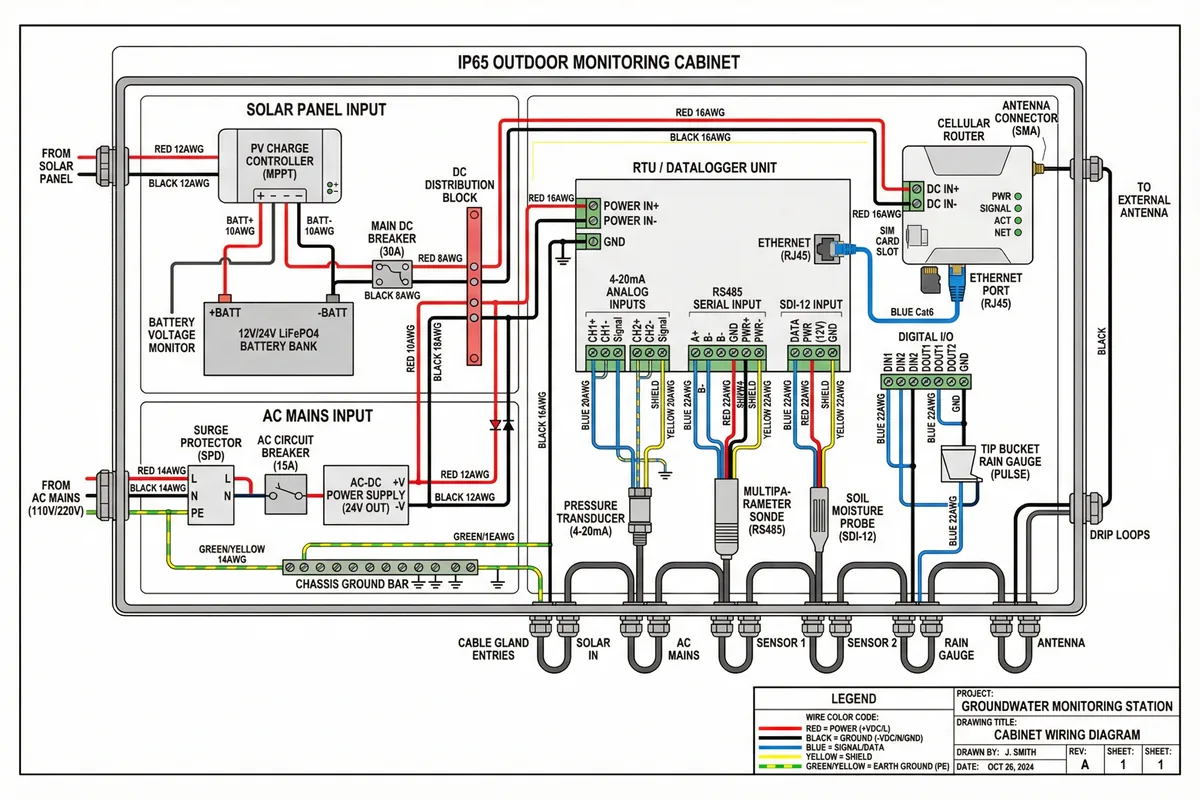
Figure 4.2: Groundwater Monitoring Station Cabinet Wiring Diagram — Complete Power, Signal, and Communications Connections with Color-Coded Wire Specifications
The wiring design follows a strict color-coding convention to facilitate troubleshooting and maintenance. Red wires carry positive DC power, black wires carry negative/ground, blue wires carry signal/data, yellow wires are shields, and green/yellow wires are protective earth. All wire sizes are specified based on current carrying capacity and voltage drop calculations, not arbitrary selection. Shield termination — grounding at one end only — is critical for preventing ground loops that introduce noise into sensor signals.
Wiring Design Rules
- Wire Sizing: Power wires sized for ≤3% voltage drop at full load; signal wires minimum 22 AWG shielded twisted pair.
- Shield Termination: Shield grounded at RTU end only; sensor end left floating to prevent ground loops.
- Surge Protection: SPD on all power entries (Type 2 minimum); signal SPD on all external cable entries.
- Cable Separation: Power and signal cables routed in separate conduits or with minimum 150 mm separation.
- Drip Loops: All cables entering the cabinet must have a drip loop below the entry point to prevent water ingress.
- Labeling: All wires labeled at both ends with wire number, source, and destination.
- Terminal Blocks: Use screw-type or spring-cage terminal blocks rated for the wire gauge; no wire-to-wire connections inside the cabinet.
- Grounding: Chassis ground bar connected to earth ground with minimum 6 AWG conductor; earth resistance <10 Ω verified at commissioning.
4.4 Power Architecture
| Power Type | Application | Key Components | Sizing Rule | Autonomy Target |
|---|---|---|---|---|
| Solar + Battery | Remote wells without mains | PV panel, MPPT controller, LiFePO4 battery | Solar: 3× daily load; Battery: 5× daily load | ≥5 days (worst-case irradiance) |
| Mains + UPS | Plant nodes, critical stations | AC input, UPS, DC PSU | UPS: 2× normal load for 2 h minimum | ≥2 h (mains failure) |
| Hybrid (Mains + Solar) | Semi-remote stations with unreliable mains | Both above, automatic transfer switch | Solar sized for mains-off periods | ≥3 days (mains failure) |