Supporting Equipment
Comprehensive coverage of all supporting equipment categories required for a complete, reliable monitoring station — from power systems and lightning protection to enclosures, communications infrastructure, sampling support, and security.
7.1 Supporting Equipment Overview
Supporting equipment — the infrastructure that enables core monitoring instruments to function reliably in the field — is frequently underspecified in monitoring system designs. Inadequate power systems, insufficient surge protection, poor enclosure selection, and weak security measures are responsible for a disproportionate share of field failures and data quality problems. The integrated diagram below shows all six supporting equipment categories and their relationships within a complete monitoring station.
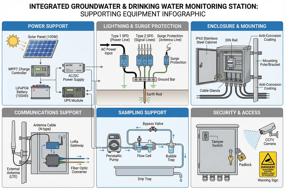
Figure 7.1: Integrated Supporting Equipment Diagram — All Six Categories (Power, Lightning Protection, Enclosure, Communications, Sampling, Security) in One Comprehensive View
The six supporting equipment categories are interdependent: the power system must be sized to support all communications and security equipment in addition to the core instruments; the lightning protection system must be coordinated with the grounding system to be effective; the enclosure must accommodate all equipment with adequate thermal management; and the security system must be powered independently to remain functional even during equipment failures. Treating these categories as isolated procurement items, rather than an integrated system, is a common design error that leads to field problems.
7.2 Power Support Systems
Power system design begins with an accurate load calculation that accounts for all equipment in the station — not just the primary sensors, but also the RTU, cellular router, security camera, heating/cooling elements, and any future expansion. The load calculation must use worst-case operating conditions (maximum temperature for cooling loads, minimum temperature for heating loads) and must include a 20% safety margin to accommodate aging and unexpected loads.
| Power Component | Specification | Selection Criteria | Common Failure Mode |
|---|---|---|---|
| Solar Panel | Monocrystalline, 20–200 W, 12/24 V | Size for 3× daily load at worst-case irradiance; tilt angle for latitude | Shading, soiling, delamination, cable damage |
| MPPT Charge Controller | MPPT efficiency ≥97%, 10–60 A, 12/24/48 V | Match to panel Voc and Isc; temperature compensation; data logging | Overtemperature, incorrect battery type setting |
| LiFePO4 Battery | 12/24 V, 20–200 Ah, -20 to 60°C operating | Size for 5× daily load; cycle life ≥2000 cycles; BMS protection | Overdischarge, cell imbalance, BMS failure |
| AC/DC Power Supply | DIN rail, 24 VDC output, 5–20 A, wide input range | Wide input range (85–264 VAC); efficiency ≥90%; overcurrent protection | Overvoltage from grid transients, overtemperature |
| UPS Module | Online or line-interactive, 300–1000 VA, ≥2 h autonomy | Autonomy for critical nodes ≥2 h; battery replacement without shutdown | Battery aging, bypass mode during maintenance |
7.3 Lightning & Surge Protection
Lightning damage is the leading cause of catastrophic equipment failure at remote monitoring stations, particularly in open terrain where monitoring poles are the highest objects for considerable distances. A coordinated surge protection strategy — addressing power, signal, and antenna lines — is essential. Surge protection devices (SPDs) must be selected and installed as a coordinated system, not as individual items, because an SPD on one line that is not coordinated with SPDs on other lines can actually increase damage by creating voltage differentials between lines.
The grounding system is the foundation of all surge protection. An earth resistance of less than 10 Ω is required for effective SPD operation. In high-resistivity soils, achieving this may require multiple earth rods in a star configuration, chemical enhancement of the soil around the rods, or a horizontal counterpoise ground system. Earth resistance must be measured at commissioning and verified annually.
| Protection Point | SPD Type | Rating | Installation Location | Coordination Requirement |
|---|---|---|---|---|
| AC Mains Entry | Type 1 + Type 2 combined | Iimp ≥12.5 kA; In ≥20 kA | At main circuit breaker | Coordinate with Type 2 at equipment |
| DC Power Lines | Type 2 DC SPD | Up ≤1.5 kV; In ≥5 kA | At RTU power input | Coordinate with AC SPD upstream |
| RS485 Signal Lines | Signal SPD, RS485 compatible | Up ≤50 V; response <1 ns | At cabinet entry, before RTU | Grounded to same earth bar as power SPD |
| Antenna Lines | Coaxial lightning arrester | N-type or SMA; DC grounded | Where antenna cable enters cabinet | Grounded to same earth bar |
| Ethernet Lines | Ethernet SPD (RJ45) | Up ≤50 V; 1 Gbps compatible | At cabinet entry | Grounded to same earth bar |
7.4 Enclosure & Mounting
Enclosure selection must balance environmental protection, thermal management, accessibility for maintenance, and physical security. The IP rating defines protection against solid particles and water ingress, but does not address corrosion resistance, UV stability, or impact resistance — all of which must be separately evaluated for the site environment. Stainless steel (316L) enclosures are preferred for coastal and high-humidity environments; powder-coated steel is acceptable for inland sites with moderate humidity; GRP (glass-reinforced polyester) is preferred for sites with corrosive atmospheres.
| Enclosure Parameter | Minimum Requirement | Recommended | Notes |
|---|---|---|---|
| IP Rating | IP65 | IP66 for flood-prone sites | Verify with water spray test at commissioning |
| Material | Powder-coated steel | 316L stainless steel or GRP | Coastal sites require stainless or GRP |
| Thermal Management | Breathable membrane vent | Thermostat-controlled fan or heater | Required if internal temp range >40°C |
| Internal Volume | 2× current equipment volume | 3× for expansion headroom | Allow for future sensor additions |
| Mounting Height | ≥0.5 m above ground | ≥1.2 m in flood-prone areas | Verify against 100-year flood elevation |
7.5 Security & Access Control
Physical security of monitoring stations is essential for maintaining data integrity and chain-of-custody compliance. Unauthorized access — whether malicious tampering or accidental interference — can compromise the evidentiary value of monitoring data and create liability issues. The security system must detect access events, record them with timestamps, and alert operators immediately when unauthorized access is detected.
| Security Measure | Function | Specification | Evidence Generated |
|---|---|---|---|
| Tamper Switch | Detect cabinet opening | Magnetic reed switch, normally closed | Timestamped open/close events in platform |
| Tamper-Evident Seals | Detect unauthorized access between visits | Numbered, destructible, weather-resistant | Seal numbers recorded in site logbook |
| Padlock | Prevent casual unauthorized access | Stainless steel, keyed-alike for site | Key log maintained by site manager |
| CCTV Camera | Visual record of all site access | IP camera, IR night vision, 30-day local storage | Video footage with timestamp overlay |
| Vibration Sensor | Detect physical impact or tampering | Piezoelectric, configurable sensitivity | Vibration events logged with timestamp |