Design Methods
Executable design principles, failure cause analysis, core selection logic, and key design dimensions that guide every decision in groundwater and drinking water monitoring system design.
2.1 Executable Principles & Basis
Effective monitoring system design requires adherence to a set of executable principles — not abstract guidelines, but actionable rules that can be verified during design review and acceptance testing. Each principle is grounded in a specific technical or regulatory basis, ensuring that design decisions are defensible and traceable. The following twelve principles form the foundation of every design decision in this guide.
- Tiered Monitoring Design: Classify all monitoring points by risk level and function (baseline/trend vs. early warning). Higher-risk points receive more frequent sampling, redundant sensors, and faster alarm latency. Basis: risk management and regulatory grading frameworks.
- Representativeness First (Groundwater): Indicator validity depends entirely on well construction quality and screened interval alignment with the target aquifer. No amount of sensor sophistication compensates for a poorly constructed or improperly purged well. Basis: hydrogeology and sampling theory.
- Early Warning Latency Targets (Drinking Water): Define maximum detection-to-alarm time for each node (e.g., ≤1–5 minutes for intake nodes). This target drives sensor selection, communication architecture, and alarm rule design. Basis: operational safety requirements.
- Hybrid Online + Offline Monitoring: Online sensors provide continuous signals for trend and early warning; offline laboratory sampling provides legal defensibility and confirmation of compliance. Neither alone is sufficient. Basis: compliance auditing requirements.
- QA/QC as Architecture, Not a Report Step: Calibration schedules, drift checks, and data flags must be enforced in the data pipeline, not added as a post-processing step. Basis: data governance and audit requirements.
- Time Synchronization as a Functional Requirement: All monitoring points must maintain bounded time error (≤2 s for plant nodes, ≤30 s for wells). Without time sync, event correlation and source tracing are unreliable. Basis: event correlation requirements.
- Fail-Safe Alarming: Define explicit system behavior for missing or invalid data. For critical nodes, "no data" must trigger an alarm — silence must never be interpreted as "all is well." Basis: safety engineering principles.
- Maintainability by Design: Use standard connectors, documented interfaces, and hot-swappable modules where possible. Design for the O&M team's skill level and spare parts availability. Basis: lifecycle cost (LCC) reduction.
- Security-by-Segmentation: Isolate OT (operational technology) networks from IT networks. Apply least-privilege access, enforce audit logs, and maintain firmware update policies. Basis: ICS/OT security best practices.
- Evidence Chain Completeness: Store calibration certificates, laboratory reports, and tamper events with immutable timestamps and access logs. Every data point must have a traceable lineage. Basis: compliance and audit requirements.
- Environmental Hardening: Select enclosure ratings, corrosion-resistant materials, and surge protection appropriate for the site's environmental extremes. Basis: reliability engineering and site survey data.
- Graceful Degradation: Define a minimal monitoring set that remains operational when partial failures occur. Critical indicators must remain available even when secondary systems fail. Basis: resilience engineering.
2.2 Failure Causes & Recommendations
Field experience across groundwater and drinking water monitoring deployments reveals recurring failure patterns. Understanding these patterns — their root causes, typical symptoms, and prevention strategies — is essential for robust system design. The table below summarizes the eight most common failure mechanisms, with specific avoidance recommendations and verification methods.
| Failure Mechanism | Typical Symptom | Root Cause | Avoidance Recommendation | Verification Method |
|---|---|---|---|---|
| Groundwater sample not representative | Inconsistent lab vs. sensor readings | Wrong screen depth, poor purge volume, well construction defects | Enforce well log review, purge volume SOP, screen interval alignment | Sampling audit + hydrogeological review |
| Analyzer bubble interference | Spikes in turbidity or chlorine readings | Bypass piping design without bubble trap, unstable flow | Add bubble trap, stabilize flow to 0.5–2 L/min, add air release valve | Commissioning flow test + spike pattern review |
| Sensor fouling | Slow drift, increasing offset from lab values | Biofilm, iron/manganese precipitation, algae growth | Antifouling options (wiper/copper), cleaning interval schedule, flow cell design | Drift KPI dashboard, periodic lab comparison |
| Time drift | Misaligned events between stations | No NTP configuration, low-cost clocks without correction | NTP/GNSS time sync at all RTUs, drift alarms for deviations >30 s | Time audit across all points |
| Alarm storms | Operators ignore or silence alarms | Poor threshold settings, no hysteresis, no suppression logic | Multi-level rules, deadband/hysteresis, suppression during maintenance | Alarm simulation, false positive rate KPI |
| Data loss during comms outage | Gaps in time series | No local buffer at RTU, insufficient storage | RTU storage ≥7–30 days, store-and-forward protocol | Disconnect test, backlog recovery verification |
| Cabinet water ingress | Repeated equipment failures, corrosion | Insufficient IP rating, missing drip loops, poor gland sealing | IP65+ enclosures, breathable membranes, drip loops, gland inspection | Water spray test, post-rain inspection |
| Lightning damage | Recurring port failures, RTU resets | Inadequate SPD coordination, high earth resistance | Coordinated SPD at power and signal entries, earth resistance <10 Ω | Earth resistance measurement, SPD status check |
2.3 Core Design & Selection Logic
The design selection process follows a structured decision tree that begins with the monitoring object type and progressively narrows to a specific station class, instrument set, and QA/QC intensity. This systematic approach ensures that design decisions are consistent, auditable, and appropriate for the site's specific risk profile and operational constraints.
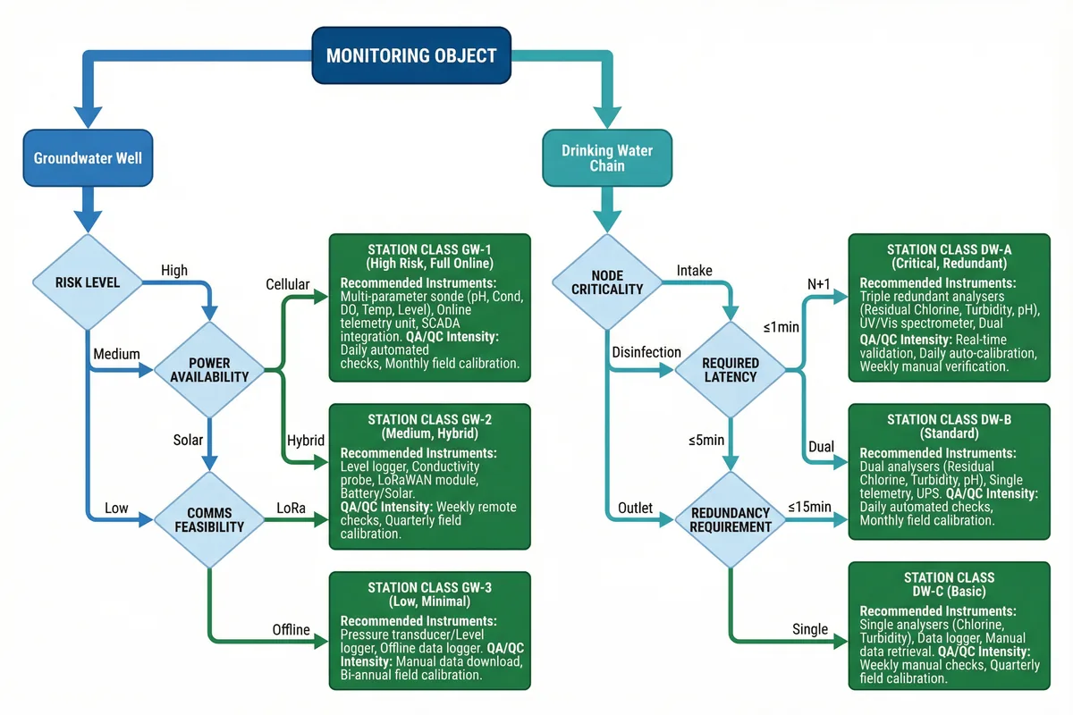
Figure 2.1: Core Design Selection Decision Tree — From Monitoring Object Type to Station Class and Instrument Configuration
For Groundwater Wells, the decision path evaluates risk level (High/Medium/Low), power availability (Mains/Solar/Hybrid), and communications feasibility (Cellular/LoRa/Offline) to arrive at Station Class GW-1, GW-2, or GW-3. For Drinking Water Chain nodes, the path evaluates node criticality (Intake/Disinfection/Outlet), required alarm latency (≤1 min/≤5 min/≤15 min), and redundancy requirements (N+1/Dual/Single) to arrive at Station Class DW-A, DW-B, or DW-C.
Design Step Sequence
- Define compliance indicators required by applicable regulations
- Classify all monitoring points by type and risk level
- Choose station class using the decision tree
- Select sensors and redundancy level for each station class
- Define sampling frequency and data transmission intervals
- Design communications and power architecture
- Define QA/QC rules and calibration schedule
- Define alarm matrix with thresholds, hysteresis, and escalation paths
- Define integration interfaces and O&M procedures
2.4 Key Design Dimensions
Every monitoring system design must be evaluated across seven key dimensions that collectively determine whether the system will meet its operational, regulatory, and lifecycle objectives. These dimensions provide a structured framework for design review and acceptance testing, ensuring that no critical aspect is overlooked.
| Dimension | Design Focus | Practical Metric | Acceptance Focus |
|---|---|---|---|
| Performance / Experience | Alarm latency from event to notification | 1–5 min (plant nodes); 30–60 min (wells) | End-to-end timed drill test |
| Stability / Reliability | System uptime and data completeness | ≥99% for critical nodes; ≥95% for wells | SLA report over 30-day period |
| Maintainability | Mean time to repair (MTTR) | <4 h (plant); <24–72 h (remote wells) | Spare parts availability audit |
| Compatibility / Expansion | Open protocol interfaces for future integration | Modbus TCP, OPC UA, MQTT, REST API | Integration test with external systems |
| Lifecycle Cost (LCC) | Total cost of ownership over 5–10 years | CAPEX + OPEX + consumables + O&M | Cost model with sensitivity analysis |
| Energy / Environment | Power budget and solar autonomy | Solar autonomy ≥5 days (worst case) | Field validation of solar sizing |
| Compliance / Certification | Audit evidence completeness | Complete CoC logs, calibration records | Audit package export and review |