Scenarios & Selection
Eight representative deployment scenarios covering the full range of groundwater and drinking water monitoring applications, each with real-scene photography, technical requirements, and measurable success metrics.
3.1 Applicability Boundaries
This design guide is applicable to a broad range of groundwater and drinking water monitoring deployments, but certain site conditions and use cases fall outside its scope. Understanding these boundaries prevents misapplication of design standards and ensures that each deployment receives appropriately specified equipment and procedures.
Applicable scenarios include regional groundwater monitoring networks, drinking-water source protection zones, intake monitoring stations, water treatment plant process online monitoring, compliance reporting systems, and emergency early warning networks. The guide is specifically designed for deployments that combine online continuous monitoring with periodic offline laboratory sampling.
Not suitable for purely research-grade high-frequency geochemical studies requiring specialized laboratory instrumentation at each point; sites with zero communications feasibility and no viable periodic visit schedule; or explosive atmospheres requiring ATEX/IECEx certified equipment beyond the scope of this guide.
Key Constraints to Evaluate Before Design
- Remote access feasibility: road conditions, seasonal flooding, access permits
- Seasonal flooding risk: determines enclosure mounting height and IP rating
- Reagent logistics: determines whether reagent-based analyzers are viable
- O&M capability: determines acceptable maintenance complexity
- Regulatory reporting cadence: determines minimum data completeness requirements
3.2 Typical Scenarios
Rural Groundwater Monitoring Wells with Solar Power
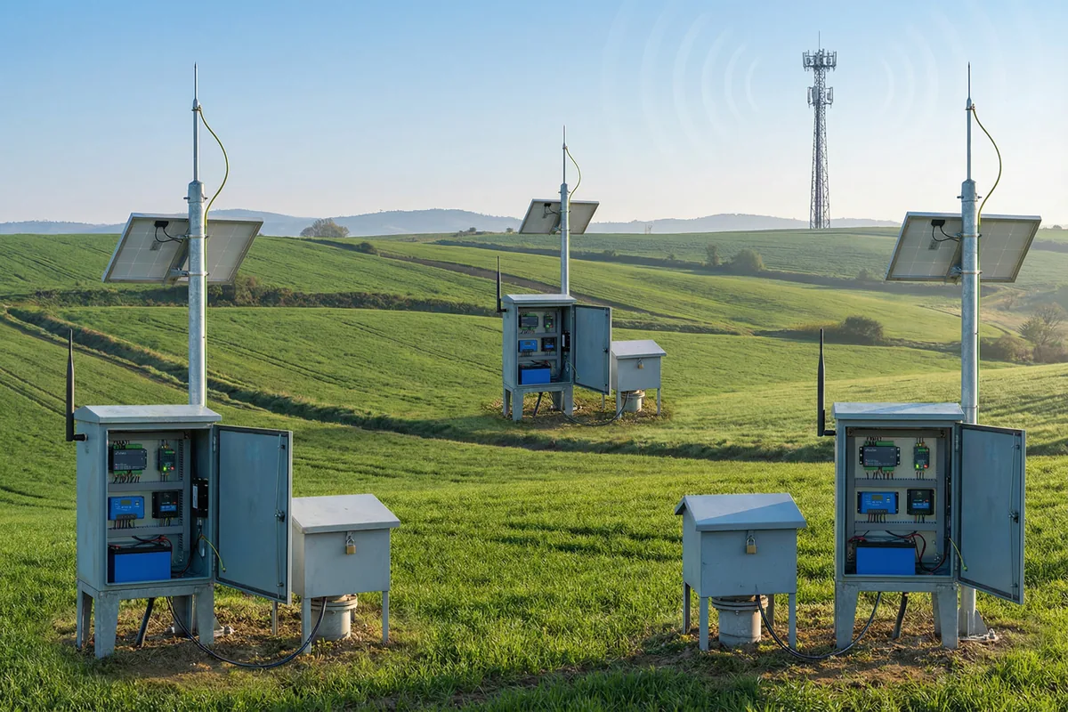
Figure 3.1: S1 — Rural Groundwater Well Network with Solar Power, Cellular Communications, and IP65 Outdoor Cabinets
Rural groundwater monitoring wells represent the most common and challenging deployment scenario, combining remote access difficulties with power instability and harsh environmental conditions. These stations are typically deployed in agricultural areas, hilly terrain, or remote protected zones where mains power is unavailable or unreliable. Solar power systems must be sized for worst-case winter irradiance conditions, not average annual values, to ensure continuous operation during extended cloudy periods.
Data must be buffered locally for a minimum of 30 days to handle extended communications outages, which are common in rural cellular coverage areas. The RTU's store-and-forward capability is critical — when connectivity is restored, all buffered data must be uploaded with original timestamps to preserve data integrity and prevent gaps in the compliance record. Monthly site visits are typically required for visual inspection, calibration verification, and consumable replenishment.
Key Requirements
Industrial Park Upgradient/Downgradient Well Pair for Source Tracing
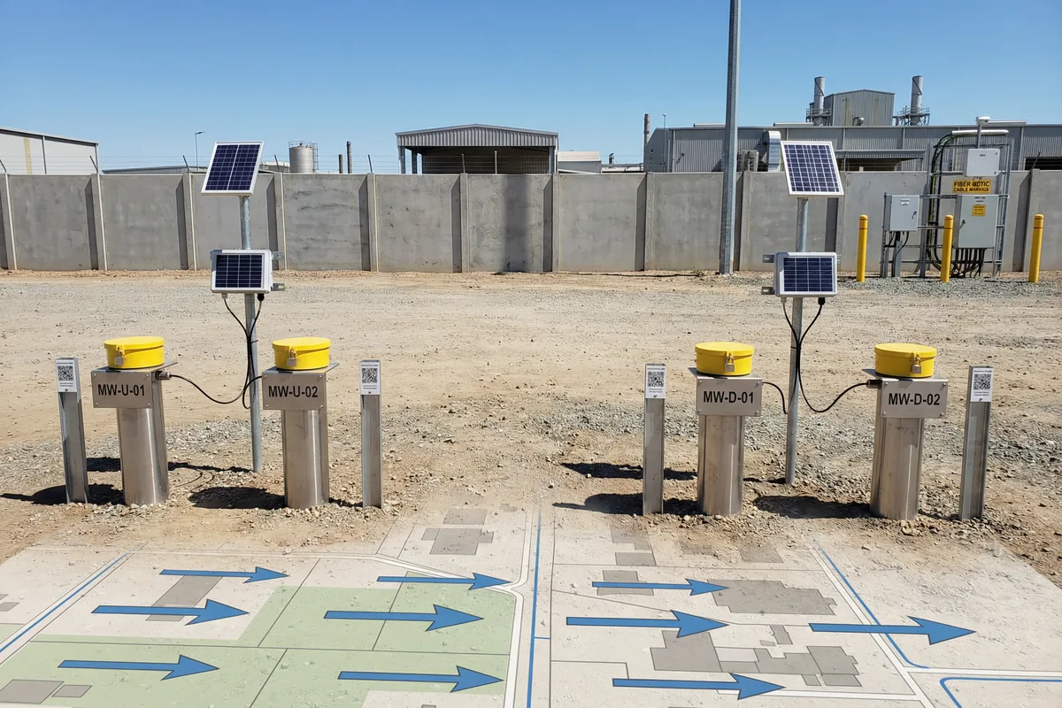
Figure 3.2: S2 — Industrial Park Well Pairs with QR Code Asset Tracking and LoRa Network for Source Tracing
Paired upgradient and downgradient monitoring wells enable differential analysis to detect groundwater contamination attributable to industrial activities. The spatial relationship between wells — their positions relative to the groundwater flow direction — is as important as the measurements themselves. Well pairs must be installed with consistent screened intervals targeting the same aquifer zone to ensure that differences in readings reflect actual contamination gradients rather than geological heterogeneity.
Legal defensibility is a primary design driver for this scenario. All data must be traceable, tamper-evident, and accompanied by complete chain-of-custody records for laboratory confirmatory samples. GIS mapping with accurate coordinates and groundwater flow direction overlays is essential for presenting evidence to regulatory authorities. Quarterly laboratory sampling with a comprehensive analyte suite is required to confirm online sensor trends.
Key Requirements
Drinking-Water Intake River Monitoring with Fast Early Warning
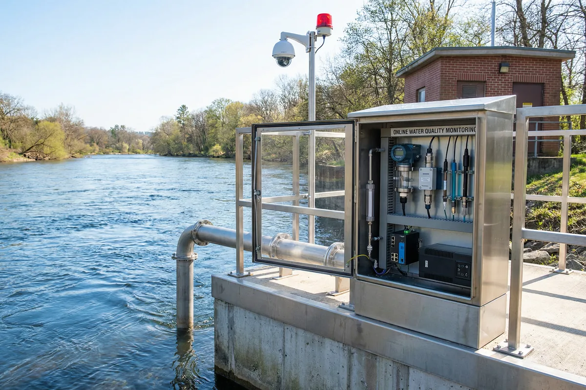
Figure 3.3: S3 — River Intake Monitoring Station with Online Water Quality Cabinet, UPS Power, and IP Camera Verification
River intake monitoring represents the highest-criticality scenario in drinking water protection, where upstream pollution events can propagate to the intake within minutes to hours. The system must detect anomalies and trigger alarms within 3 minutes of the event reaching the monitoring point — this latency target drives every design decision, from sensor selection and bypass flow design to communications redundancy and alarm rule configuration.
Redundancy is non-negotiable at this station class. Dual communications paths (fiber primary, LTE backup) ensure that alarm notifications reach operators even during network maintenance or failures. UPS autonomy of at least 2 hours protects against power outages during storms, which are often correlated with upstream pollution events. The "no-data alarm" must be configured so that communications failure triggers an immediate alert rather than silent data gaps.
Key Requirements
Water Plant Disinfection Node (Residual Chlorine) with Process Linkage
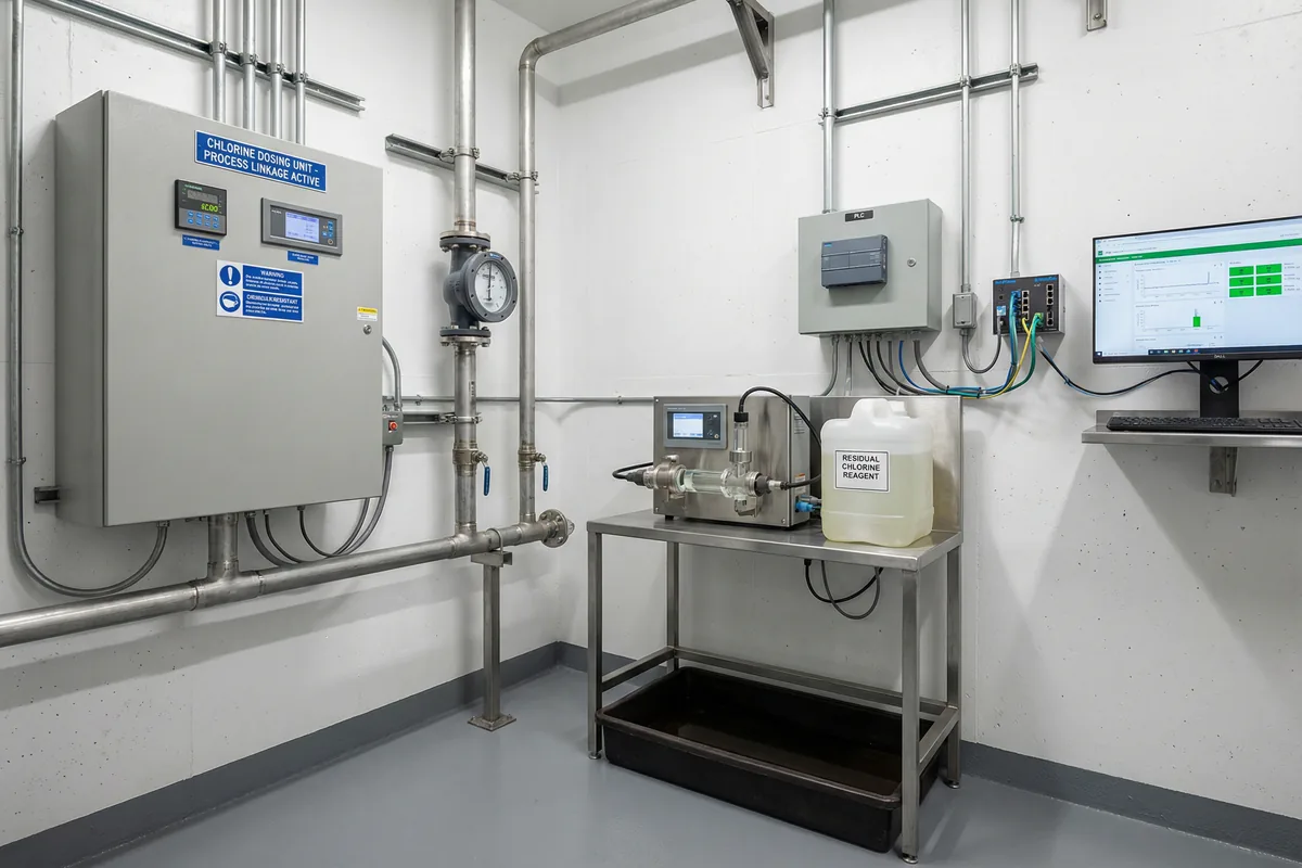
Figure 3.4: S4 — Water Plant Disinfection Node with Residual Chlorine Analyzer, Reagent Management, and PLC Process Linkage
The disinfection node is the most safety-critical measurement point in the water treatment process. Residual chlorine readings directly inform dosing decisions, and both under-dosing (public health risk) and over-dosing (taste/odor complaints, byproduct formation) have significant consequences. The analyzer must be integrated with the PLC control system so that alarm states can trigger automated dosing adjustments or operator alerts within the required response time.
Reagent logistics dominate the reliability profile of this node. Reagent depletion is the leading cause of analyzer downtime and false readings. A reagent level sensor with low-stock alarm must be configured to trigger a resupply work order well before depletion. Chemical corrosion protection — drip trays, chemical-resistant materials, and appropriate ventilation — is essential given the chlorine environment.
Key Requirements
Distribution Outlet Monitoring for Compliance and Consumer Protection
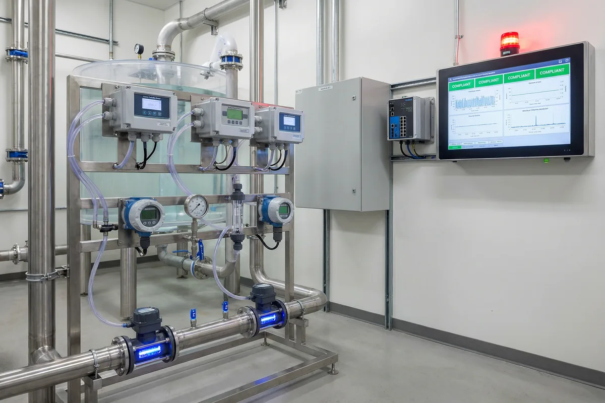
Figure 3.5: S5 — Distribution Outlet Monitoring with Stainless Steel Bypass Rack, Real-Time Display, and Compliance Data Logging
Distribution outlet monitoring focuses on long-term compliance, auditability, and consumer protection rather than real-time emergency response. The primary design drivers are data immutability, report reproducibility, and integration with regulatory reporting portals. Every parameter change, calibration event, and maintenance action must be logged with timestamps and operator identity to support annual audit reviews.
Redundancy for critical sensors (turbidity and residual chlorine) ensures that compliance data gaps do not occur due to single-sensor failures. Role-based access control prevents unauthorized parameter changes, and all access attempts must be logged. Data retention of at least 5 years is required for regulatory compliance, with the last 2 years maintained in queryable "hot" storage.
Key Requirements
Flood-Prone Wells Requiring Elevated Installation and Water Ingress Defenses
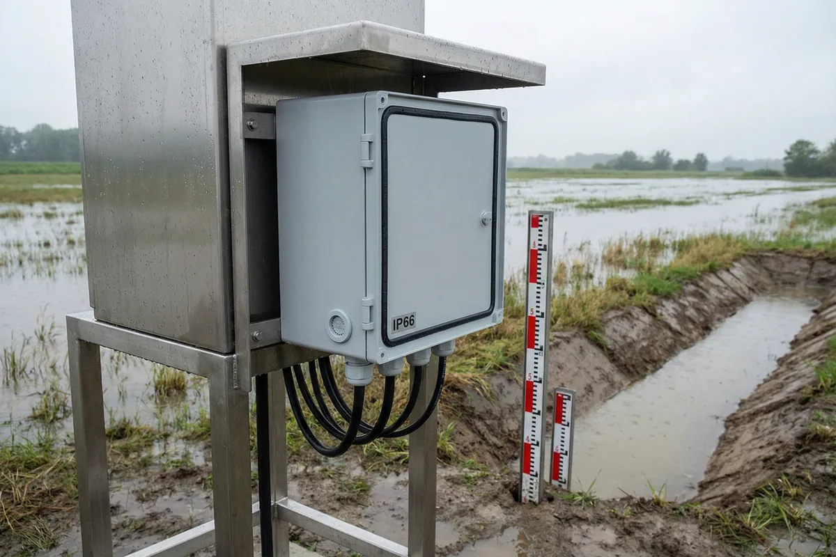
Figure 3.6: S6 — Elevated Cabinet Installation on Steel Bracket Stand with IP66 Enclosure and Water Level Warning Markers in Flood-Prone Area
Flood-prone monitoring sites present a unique challenge: the very hydrological events that make monitoring most important — storm events, high-water periods — are also the conditions most likely to damage monitoring equipment. Elevated mounting of cabinets and equipment above the design flood elevation is the primary defense, but must be combined with IP66 cable glands, conformal coating on electronics, and water ingress sensors that trigger alarms before flooding reaches critical equipment.
Post-flood recovery procedures must be defined in advance, including a checklist for verifying equipment integrity, recalibrating sensors that may have been submerged, and validating data continuity. Surge protection must be rated for the increased lightning risk during storm events. Drip loops on all cable entries prevent water from tracking along cables into the enclosure.
Key Requirements
Multi-Source Water Supply with Blending and Complex Alarms
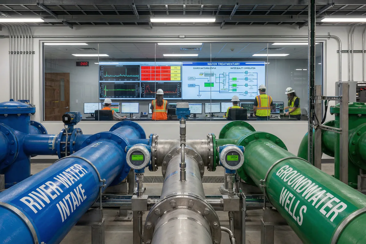
Figure 3.7: S7 — Multi-Source Water Treatment Plant with River Water (Blue) and Groundwater (Green) Blending, Conductivity and UV254 Monitoring
Multi-source water supply systems present a unique alarm management challenge: water quality baselines change whenever the source blend ratio changes, making fixed-threshold alarms unreliable. A switch from river water to groundwater, or a change in blending ratio, will cause step changes in conductivity, UV254, and other parameters that would trigger false alarms if static thresholds are used. Dynamic threshold adjustment based on source status tags is essential.
The platform must receive source switching status tags from the SCADA/DCS system and use these to apply the appropriate baseline and threshold set for the current source configuration. Operator training is critical — operators must understand why alarms behave differently under different source configurations, and the alarm system must provide explanatory context rather than just raw threshold violations.
Key Requirements
Remote Protected Source Zone with Strict Anti-Tamper and Chain-of-Custody

Figure 3.8: S8 — Protected Water Source Zone with Double-Lock Cabinet, Numbered Tamper Seals, and Mobile Chain-of-Custody App
Protected source zone monitoring places regulatory and legal defensibility on equal footing with measurement quality. Every access event, sampling action, and equipment change must be documented with timestamps, operator identity, and photographic evidence. The system must be designed to withstand scrutiny in regulatory proceedings and, potentially, legal disputes about contamination liability.
Physical security measures — double locks, tamper-evident numbered seals, vibration sensors, and CCTV — are as important as the monitoring instruments themselves. The mobile chain-of-custody application must function in offline mode for sites without connectivity, synchronizing records when connectivity is restored. Cryptographic signing of records ensures that digital evidence cannot be altered after the fact.
Key Requirements
3.3 Scenario → Solution Mapping Matrix
The table below provides a concise reference mapping each scenario to its recommended station class, online and offline monitoring sets, communications approach, power strategy, and redundancy requirements. This matrix serves as a starting point for system design and should be refined based on site-specific survey results.
| Scenario | Station Class | Online Set | Offline Set | Comms | Power | Redundancy |
|---|---|---|---|---|---|---|
| S1 Rural Wells | GW-2 | Level + Temp, optional EC | Quarterly lab suite | LTE | Solar + Battery | Buffer + spare sensor |
| S2 Industrial Pairs | GW-1 | Level + EC + ORP | Monthly lab confirm | LoRa → Gateway | Mains/Solar | Paired wells |
| S3 Intake River | DW-A | Turbidity + UV254 + EC + pH | Event grab sampling | Fiber + LTE | UPS | Dual comms |
| S4 Disinfection | DW-A | Residual chlorine + backup | Daily/weekly grab | Ethernet | UPS | Analyzer + backup method |
| S5 Distribution | DW-B | Turbidity + Chlorine + Pressure | Monthly compliance | Ethernet | UPS | N+1 critical sensors |
| S6 Flood-Prone | GW-2 Hardened | Level + Temp | Quarterly | LTE | Solar | Ingress sensors |
| S7 Multi-Source | DW-A/B | Blending indicators | Confirmatory | Ethernet | UPS | Contextual rules |
| S8 Protected Zone | GW-1 + Security | Level + key risk indicators | Strict CoC | LTE | Mains/Solar | Tamper + logs |
3.4 Solution Comparison
| Option | Description | Pros | Cons | Best Fit |
|---|---|---|---|---|
| A | Minimal online + heavy lab sampling | Legally defensible, lower CAPEX | Slow anomaly detection, high lab costs | Low-risk baseline monitoring |
| B | Hybrid balanced online + offline | Good cost-performance ratio | Requires QA/QC discipline | Most groundwater projects |
| C | High online redundancy, minimal offline | Fastest warning, high uptime | Higher CAPEX/OPEX, reagent logistics | Critical intakes and plant nodes |
3.5 Recommended Indicator Ranges
| Indicator | Groundwater Trend Range (Typical) | Drinking Water Operational Range (Typical) | Notes |
|---|---|---|---|
| Water Level | Site-specific | N/A | Focus on change rate, not absolute value |
| pH | 6–9 | 6.5–8.5 | Confirm with lab; electrochemical drift common |
| Conductivity (µS/cm) | 50–5000 | 50–1500 | Excellent source tracing indicator |
| Turbidity (NTU) | 0–50 (in-well) | 0–5 (finished), raw higher | Alarm at intake for sudden increases |
| Residual Chlorine (mg/L) | N/A | 0.2–1.0 (typical target) | Compliance limit varies by jurisdiction |
| UV254 (1/m) | 0–50 | 0–30 | Natural organic matter surrogate |
| ORP (mV) | -200 to +400 | N/A (process use) | Redox indicator for contamination |