Installation Requirements
Site preparation, civil works, mechanical installation, electrical connections, commissioning procedures, and acceptance testing requirements for groundwater and drinking water monitoring stations.
11.1 Installation Overview
Proper installation is the foundation of a reliable monitoring system. Even the best instruments will underperform or fail prematurely if installed incorrectly. Installation quality issues — poor grounding, inadequate cable support, incorrect sensor placement, insufficient weatherproofing — are responsible for a significant proportion of field failures and data quality problems. The installation requirements in this chapter represent minimum standards; site-specific conditions may require more stringent measures.
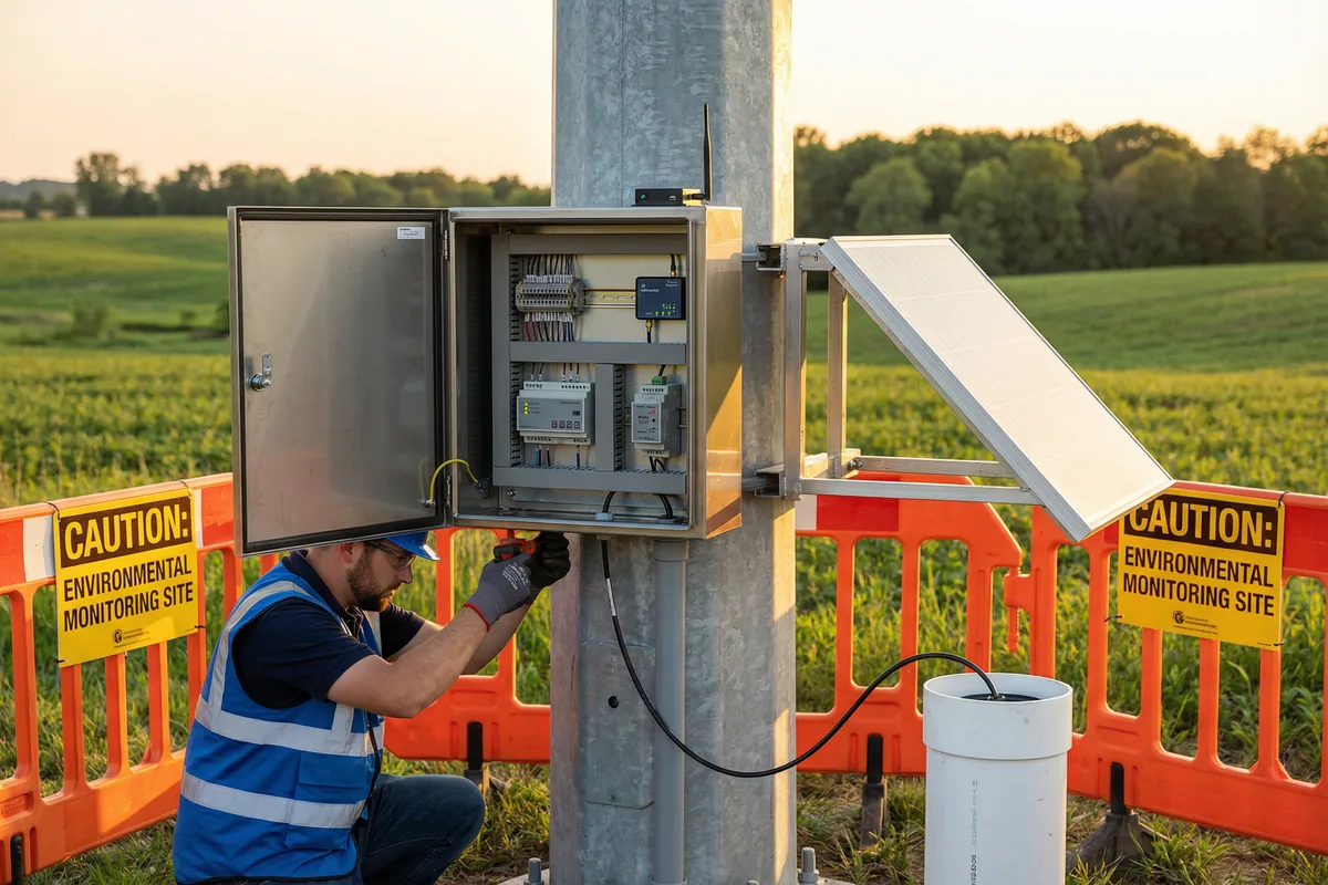
Figure 11.1: Monitoring Station Installation — Technician Installing Cabinet on Galvanized Steel Pole with Solar Panel, Organized Internal Wiring, and Submersible Sensor Cable to Well Casing
The installation process follows a defined sequence: site preparation and civil works; mechanical installation (pole, cabinet, solar panel); electrical installation (power, grounding, surge protection); instrument installation (sensors, RTU, communications); software configuration and commissioning; and acceptance testing. Each stage must be completed and verified before proceeding to the next. Rushing through stages — particularly grounding and surge protection — creates latent vulnerabilities that may not manifest as failures until the first lightning event.
11.2 Site Preparation Requirements
| Preparation Item | Requirement | Verification Method | Responsible Party |
|---|---|---|---|
| Site Access | All-weather vehicle access to within 50 m of station; locked gate with key provided to operator | Site inspection; key handover documented | Site owner / client |
| Foundation | Concrete pad (min 600×600×600 mm) for pole base; cured ≥28 days before installation | Concrete test certificate; curing period verified | Civil contractor |
| Earth Rod | Copper-clad earth rod (min 1.8 m), driven to achieve <10 Ω earth resistance | Earth resistance test with calibrated tester; result recorded | Electrical contractor |
| Cable Conduit | Underground conduit from cabinet to well/sensor location; min 50 mm diameter; sealed at both ends | Visual inspection; pressure test for underground sections | Civil contractor |
| Cellular Signal | Minimum -90 dBm signal strength at site for primary carrier; -95 dBm for backup carrier | Signal survey with handheld meter; results recorded | Installation team |
| Safety Clearances | Minimum 3 m clearance from overhead power lines; minimum 5 m from any fuel storage | Site measurement; documented in installation report | Installation team |
11.3 Mechanical Installation Requirements
- Pole Installation: Hot-dip galvanized steel pole, minimum 60 mm OD, set in concrete foundation. Pole must be plumb within 1° of vertical. All pole-to-foundation connections must be sealed against water ingress.
- Cabinet Mounting: Cabinet mounted at 1.2–1.5 m center height for easy access. All mounting hardware stainless steel grade 316. Cabinet door must open fully without obstruction. Drip edge above door opening required.
- Solar Panel Mounting: Panel tilt angle set to site latitude ±5°. Panel oriented within 10° of true south (northern hemisphere) or true north (southern hemisphere). Panel must not be shaded by pole, cabinet, or vegetation at any time of day.
- Cable Management: All external cables supported at maximum 500 mm intervals. Cable entry to cabinet via IP68-rated cable glands. Drip loops on all cables entering cabinet. Cable trays or conduit for all runs exceeding 300 mm.
- Sensor Deployment: Submersible sensors secured with stainless steel cable clamp at well head. Sensor cable not kinked or abraded. Sensor depth verified and recorded. Sensor positioned to avoid pump interference and sediment disturbance.
11.4 Electrical Installation Requirements
| Electrical Item | Requirement | Test / Verification |
|---|---|---|
| Grounding System | Earth resistance <10 Ω; all equipment chassis bonded to earth bar; single earth reference point | Earth resistance measurement with fall-of-potential method; continuity test of all bonds |
| Surge Protection | SPD on all power and signal lines; SPD connected to same earth bar as equipment ground | Visual inspection of SPD status indicators; SPD test voltage verified |
| Power Wiring | Wire gauge per voltage drop calculation; all connections on terminal blocks; no wire-to-wire connections | Voltage drop measurement at full load; insulation resistance test (>1 MΩ) |
| Signal Wiring | Shielded cable for all analog signals; shield grounded at RTU end only; RS485 termination resistors installed | Signal integrity test; loop resistance measurement; RS485 communication test |
| Circuit Protection | Fuse or circuit breaker on each circuit; rated for circuit current; accessible for maintenance | Fuse/breaker rating verified against circuit current; operation test |
11.5 Commissioning & Acceptance Testing
Commissioning is the systematic process of verifying that all installed equipment operates correctly and meets the specified performance requirements before handover to the operator. A thorough commissioning process prevents latent defects from becoming operational problems and provides the baseline documentation needed for ongoing maintenance and troubleshooting. Commissioning must be witnessed by the client representative and all results recorded in a commissioning report.
| Commissioning Test | Method | Pass Criterion | Documentation |
|---|---|---|---|
| Sensor Calibration | Calibrate all sensors with traceable standards; record as-found and as-left values | All sensors within specification after calibration | Calibration certificate for each sensor |
| Data Transmission Test | Verify data received at platform from all sensors; check timestamps and units | 100% of configured parameters received; timestamps within ±30 s of UTC | Platform data screenshot with timestamps |
| Alarm Test | Simulate each alarm condition; verify notification received by all configured contacts | All alarms triggered and notifications received within specified time | Alarm test log with timestamps and contacts notified |
| Power Failure Test | Disconnect primary power; verify system continues operating on backup; restore power | No data loss during switchover; system resumes normal operation on power restore | Power failure test log |
| Store-and-Forward Test | Disconnect communications; verify data stored locally; restore communications; verify data uploaded | All data stored during outage successfully uploaded after reconnection | Data continuity verification report |
| Security Test | Open cabinet door; verify tamper alarm received at platform | Tamper alarm received within 60 s of door opening | Security test log |